We believe meaningful innovation comes from incremental changes grounded in proven principles. Built on decades of research, design, and hands-on industry experience, our approach combines a deep understanding of the fundamental physics of separation with lessons learned from generations of equipment. We identify what works, understand what can work better, and engineer purposeful improvements that deliver measurable results in the field.
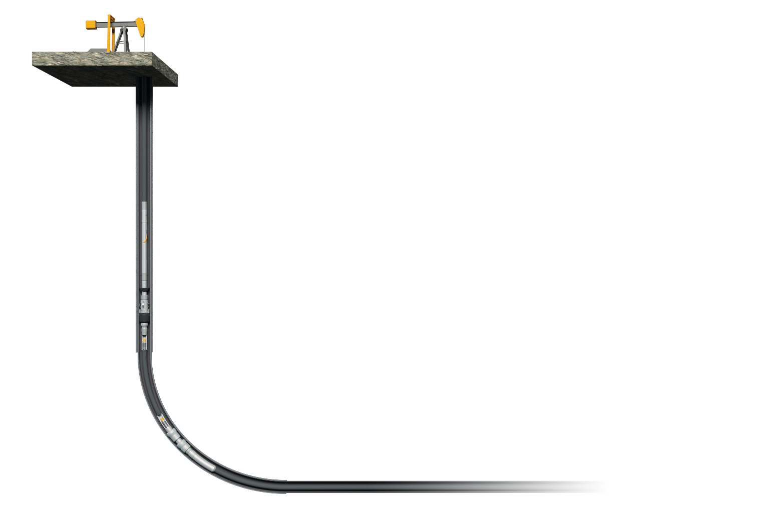
Bottom hole assemblies (BHAs) play a critical role in artificial lift performance and sustained well production. Protecting that performance starts with addressing gas and solids at the source, rather than managing their effects farther uphole. Horizontal completions changed the equation: longer laterals, increased gas interference, and different slugging behavior create challenges that many traditional separator designs were never built to handle.
Gas interference reduces efficiency, wastes energy, and lowers production. Left unmitigated, it leads to fluid and gas hammering — increasing wear and downhole failures, including rod parting and tubing wear.
Wells are also pumping — and producing back — more sand than ever before, as frac operations push larger proppant volumes into longer laterals. That sand doesn't stay in the formation; it flows back with production, accelerating wear on pumps, rods, and tubing, and driving more frequent failures across the string.
The same principle that separates oil and water separates gas and fluid downhole.
Gas is lighter than liquid, so it rises to the top — the same reason oil floats on water. It's the simplest principle in the system, and it's the starting point for every gas separator design: give the gas room and time to break away and rise, before the fluid stream continues on to the pump.
Shake the two fluids together, then watch density sort them back into layers — gold rises, blue settles.
Settled — lighter oil sits on top.
No matter how hard you shake it, the denser fluid always ends up back on the bottom. It's not random — every droplet is pulled by the same force, in the same direction, every time. That reliability is what a separator design leans on.
How fast gas actually separates — and how far it travels in a single pump stroke.
In lab experiments with water and air, the air escapes upward at roughly 6 inches per second. In actual oil and gas wells, that rate decreases — real fluids are more viscous, and the geometry is more complex.
At 6 spm with a 10-second revolution split roughly in half between pump-on and pump-off, gas gets about 5 seconds to rise per stroke. At 6 in/sec, that's approximately 30 inches of rise in a single stroke. That number sets the effective length a separator needs: too short and gas never clears the intake; long enough and the separator also has room to pass slugs without gas reaching the pump, which protects fluid deliverability from stroke to stroke.
The relationship is simple: V = Q / A — velocity equals flow rate over area. A liquid column with 1 square inch of cross-sectional area traveling at 6 in/sec works out to a flow rate of roughly 50 BPD — in theory, that's how much gas-free fluid a square inch of separation area should be able to hand off.
A conventional downhole gas separator, however modern, is built around the same five components.
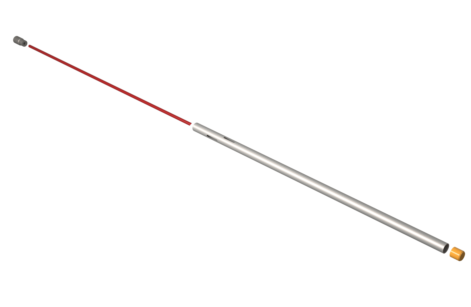
Hydrocyclones use rotation and momentum, not filters, to pull solids and gas apart from fluid.
A hydrocyclone removes particulates from a gas or liquid stream without filters, through vortex separation — rotational force and gravity working together on a mixture of solids and fluid.
Momentum is mass times velocity, so doubling the velocity doubles the particle's momentum: the particle wants to keep going straight, while the fluid around it is forced to turn. That difference is what throws solids to the outer wall while cleaner fluid continues through the center.
A modern spiral routinely generates on the order of 10–50 times the force of gravity — far beyond what simple gravity settling alone can achieve in the same length of tool.
Turn up the spin. Watch which particles get thrown to the wall first — and which ones barely move.
At rest — nothing separating yet.
Centrifugal force scales with mass and velocity — bigger particles carry more momentum at the same spin, so they get thrown outward first. Smaller particles need much higher velocity before the same force can overcome the fluid drag holding them near center.
Stokes' Law for quartz sand in water — smaller particles take dramatically longer to settle.
| Sand size | Settling velocity | Time to drop 5 ft |
|---|---|---|
| 100 mesh / 149 micron | ~1.2 in/sec | ~50 sec |
| 100 micron | ~0.70 in/sec | ~1.4 min |
| 75 micron / 200 mesh | ~0.45 in/sec | ~2.2 min |
| 50 micron / 300 mesh | ~0.23 in/sec | ~4.4 min |
| 44 micron / 325 mesh | ~0.18 in/sec | ~5.6 min |
| 25 micron | ~0.06 in/sec | ~16 min |
Large solids fall. Fine solids follow the fluid. Gravity-based separation works when particles have enough settling velocity and inertia to leave the flow stream — but as the table above shows, that velocity drops off fast as particle size shrinks. Fine solids don't settle out in time, which is why Vannevar uses rotational acceleration to force separation rather than relying on gravity alone.
Settling velocity decreases with particle diameter squared — making fine solids increasingly difficult to separate within the limited residence time available downhole. Rather than waiting for solids to fall, we generate centrifugal force to actively drive them out of the production stream.
Bench testing shows a gravitational/momentum separator working to push solids away from the pump intake — from low flow rate to high flow rates, the solids keep following the flow path instead of dropping out, and get pulled up into the pump. It's a clear illustration of why gravity and a little momentum alone often isn't enough: without active separation, fine solids just ride the stream straight to the intake. A hydrocyclone, for example, is capable of 500+ g, whereas gravitational separators on the market generally generate a g-force of around one.
Every well is different, and nobody has the 100% correct answer for all of them.
Fluid type, rate, pressure, sand size and gas all change what works downhole. Water separates sand more easily than oil, emulsions make it harder, and gas can help or hurt depending on how much there is. That is why there is no one-size-fits-all separator: one tool and one size cannot be the answer for every well.
Improvement comes from iteration. Size the tool from the best data available, run it, pull it, see what happened, and adjust. Each step gets closer to the right answer for that well. Our calculators are the starting point for that process, not the end of it, and their results are calculated, and actual performance will vary with how the well produces.
Start from the well's rate, fluids, gas and sand.
Put it in the well and let the data come in.
Pull it, look at what happened, compare with the calculation.
Refine the size, the tool or the setup, one step at a time.
A rod pump is a close-tolerance machine, and sand is what it tolerates least.
Plunger-to-barrel clearance is small. Solids that reach the pump act like grit between the two surfaces and shorten run life.
When flow stops, suspended solids settle on top of the pump and around the plunger. Restarting a stuck pump is where many sand-related failures begin.
A gas separator is built to move gas, not to clean up solids. Fine sand follows the fluid, as the settling table shows, so it takes an active desander stage behind the gas separator.
Sand separates several times faster in water than in light oil, emulsions at mid water cuts are the hardest case, and gas can help or hurt. So separating sand is never a one-size answer.
A spiral separates by spinning the fluid, and how hard it spins depends on how fast the fluid moves through it. Matching the spiral to the well's flow rate gets the most out of every barrel and is the sizing step. Try it in the desander spiral calculator.
Separation area is only one input. Every item below affects how the whole system performs, from gas separation to slug handling and fluid deliverability.
Size, count and placement of the intake windows set the inlet velocity and where fluid enters the annulus. Larger windows slow the fluid and cut turbulence at the entry, so more gas has a chance to break away.
The gap between the dip tube OD and the housing ID (and between the housing and casing) sets the downward liquid velocity. Separation area alone doesn't tell you this; annular geometry does.
A tubing anchor catcher in the flow path can restrict the annulus and create backpressure. How the TAC is built, or bypassed, changes how freely gas migrates up the casing.
Effective length decides how much time gas has to rise per stroke, how well slugs are absorbed, and how much fluid the pump sees on each fillage.
In deviated wellbores the separator rests against the low side of the casing. Gas rises along the high side, flow paths shift, and the vertical distance gas must travel changes.
Free gas separates more easily than gas still in solution. Pressure drop across the windows and through the separator drives breakout, so intake pressure and fluid properties matter.
Laminar flow lets bubbles rise undisturbed. Turbulence from high velocities or abrupt geometry changes drags gas back down with the liquid.
Spiral designs add centrifugal force to gravity, pulling heavier fluid and solids outward so gas can move to the center, a much stronger effect than gravity alone.
This page draws from Vannevar's internal BHA training curriculum. Proprietary R&D benchmarking and competitive spiral-sizing data are kept out of the public version — contact your Vannevar engineering representative for the full training program.